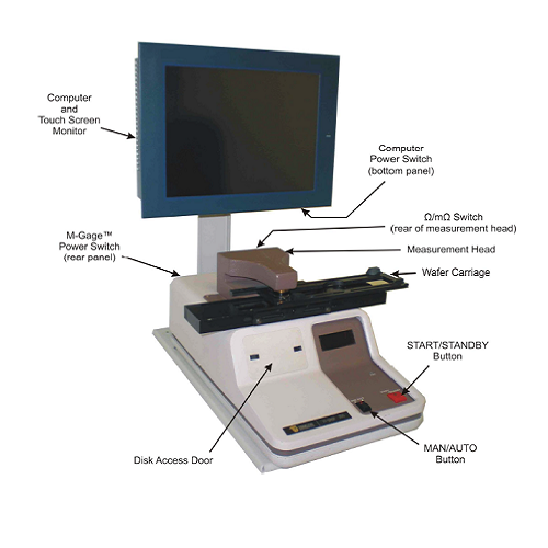
Description
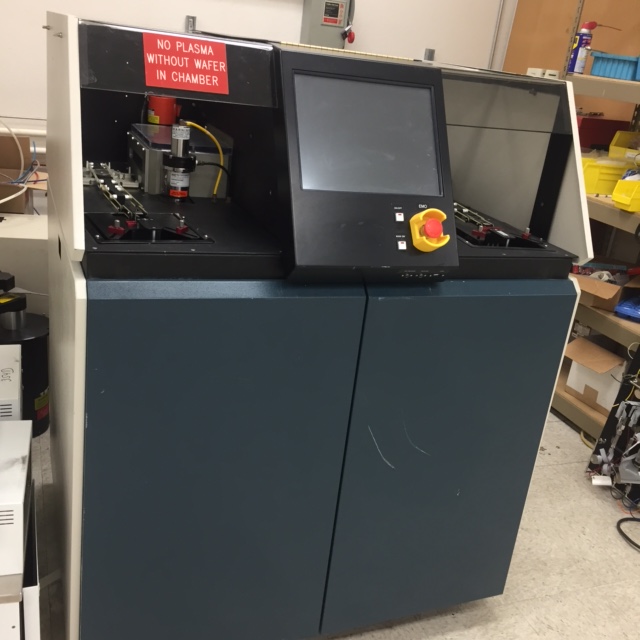
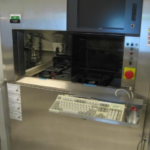
Model: Lam AutoEtch 590, the most popular model for 4 to 6 inch wafer plasma etcher. The gap between top and bottom electrode is adjustable, which make the etcher more flexible with much better performance.
Category: Plasma Etch
Original Equipment Manufacturer: Lam Research
Main Etcher Materials: SiO2 etc.
Condition: Complete, Working Condition, fully tested before shipping by seller. New PC controller with touch Screen Monitor, 6 gas lines with 5 MFC, ENI RF Generator. Refurbished condition is also available at extra cost.
Wafer Size: 4 or 6 inch configuration
Quantity: 4-5 sets are available.
Valid Time: Subject to prior sale.
Lead Time: 10-24 weeks for fully tested condition.
Location: Morgan Hill, CA, U.S.A.
Warranty: 6 months non-consumable parts warranty for fully tested condition.
Installation and training: Available at extra charge for refurbished condition
Service Contract: Available at extra charge
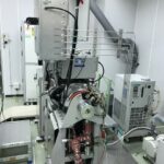
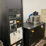
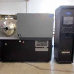
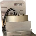
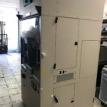
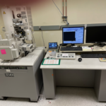
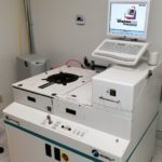
SemiStar Corp. may provide certain information related to equipment offered for sale. Any and all such information is unverified and, therefore, supplied for information purposes only without guarantees or warranties of any kind. This picture is representative of the Lam AutoEtch 590 available.
Fully Refurbished and Upgraded Lam AutoEtch VS Upgrading Lam AutoEtch VS Original Lam AutoEtch
| Comparing Item | Fully Refurbished and Upgraded Lam AutoEtch | Upgraded Lam AutoEtch | Original Lam AutoEtch |
| Controller | New PC | New PC | Z-80 MPU |
| Monitor | 15 inch Touch Screen | 15 inch Touch Screen | OLD CRT, Obsolete |
| User Interface | GUI | GUI | Text |
| Data Storage | GUI | GUI | None |
| Recipe Edit | Easy to edit with GUI | Easy to edit with GUI | Card, Obsolete |
| On Line Help | Yes | Yes | None |
| Gas Calibration | Easy to do with GUI | Easy to do with GUI | None |
| Diagnostic Function | More functions and I/O hardware “exposed” for easier maintenance and trouble shooting | More functions and I/O hardware “exposed” for easier maintenance and trouble shooting | Limited. Difficult Troubleshooting |
| A/D Precision | 14-16bits | 14-16bits | 12bits |
| EOP Function(Option) | New Method | New Method | Old Method, NOT good. |
| GEM/SEC II function (Option) | Yes if necessary | Yes if necessary | No |
| Alarm Light Tower (Option) | Yes if necessary | Yes if necessary | No |
| Multiple Wafer Sizes (Option) | Yes if necessary | Yes if necessary | No |
| PCB | New STD | New STD | Used |
| Valves | New filter kit | Used | Used |
| Meters | Used, calibrated if necessary | Used | Used |
| MFC | Calibrated | Used | Used |
| Gas lines | Polished | Used | Used |
| Chamber | Cleaned | Used | Used |
| Top/Bottom Electrodes | Cleaned, New if necessary | Used | Used |
| Door | Re-anodized if necessary | Used | Used |
| O Ring | New | Used | Used |
| RF Power | Used, calibrated | Used | Used |
| RF Match | Used, calibrated | Used | Used |
| Ceramic Ring | Cleaned | Used | Used |
| Cables | Used, New if necessary | Used | Used |
| Wires | Used, New if necessary | Used | Used |
| Stability | Best | Better | Limited |
Lam AutoEtch 590 description for reference only.
1.1 The Lam Research Corporation (LRC) Lam AutoEtch590 is an in-Line cassette to cassette, fully automated, single wafer, double air-locked, parallel plate plasma etching system. The etching program is saved on a recipe programming module. The entire Lam AutoEtch590 system is under automatic , closed-loop feedback control and is double keylocked to prevent accidental alteration of the process.
The Lam AutoEtch590 has a CRT monitor display for monitoring the machine status and the process parameters. The operating pressure, RF power, electrode spacing, gas flow rates, and step terminating modes are programmable for each step.
1.2 Lam AutoEtch590 plasma etcher plasma etch semiconductor equipment Process Chamber
A wafer is transferred from a send cassette to the entrance station. From the entrance station, it moves into an entrance air lock and then into the process chamber where it is etched by a computer controlled gas plasma discharge. The wafer is then moved from the process chamber to the exit airlock, from the exit airlock to the exit station, and is finally transported to the receive cassette. The double airlocks allow the process chamber to remain under vacuum at all times. The process chamber is located behind the operator Interface display. The operator interface is hinged and will swing up allowing visual access to the process chamber.
The process chamber is equipped with quartz windows on the front and back. Each· window has a wire mesh screen to contain the RF field and a plexiglass cover for UV filtering. The windows at low for observation of the etching process. The front window plate also serves as the mounting point for the capacitance manometer and a pressure switch.
The major sub-systems of ·the process chamber are: the Iower electrode assembly, the electrode gap drive, the upper electrode, and the RF match assembly. The chamber is anodized in order to prevent reaction with the etching gases. Care must be exercised to prevent damage to this anodized coating.
Lam AutoEtch590 Lower Electrode Assembly
The lower electrode assembly contains the lower electrode or anode on which the wafer rests during wafer processing. The entrance arm transports the wafer from the entrance airlock into the process chamber and positions it over a lifter. The lifter picks up the wafer and then lowers it onto the anode. When the process cycle Is complete, the lifter raises the wafer and sets It on the exit arm which transports it to the exit air lock. This chamber lifter is moved up and down by a pneumatic cylinder. The position of the lifter is sensed by two limit switches on the lifter drive cylinder and this information Is fed back to the computer. A resistance thermometer device (RTD), located on the electrode Insert assembly,
sends temperature data to the CPU which monitors the temperature of the anode.
A temperature controller heats or cools ethylene glycol that is circulating through the lower electrode, maintaining the desired anode temperature. A chiller may also be used to control the anode temperature.
Lam AutoEtch590 Electrode Gap Adjustment System
The electrode gap adjustment system provides for adjustment of the space between the cathode and the wafer. The electrode gap Is adjusted by moving the upper electrode up or down with four DC motors. The motors drive four lead screws which are ganged and synchronized with a common chain to Insure parallelism between the cathode and the anode. The position of the upper electrode is sensed by a 10-turn precision potentiometer. Two limit switches prevent the upper electrode from driving too far In either direction. In addition there are mechanical stops which prevent the upper electrode from making contact with the lower electrode.
A electrical brake system is incorporated to overcome the force exerted on the cathode when the chamber is at vacuum. This force is relatively large and moves the upper electrode downward when power is removed from the drive motors. Without a brake, the cathode would be forced out of position at the same time the DC motors attempt to reposition the cathode, causing an oscillation of the gap adjustment drive system. The gap drive brake automatically locks the gap housing in position whenever power is removed from the four drive motors.
The gap housing has two large flange ( Bal ) seals which provide a differentially pumped space between the chamber and atmospheric pressure.
Lam AutoEtch590 Upper Electrode Assembly
The upper electrode assembly consists of an insulator ring, baffles, and the cathode. The process gases flow through a gas manifold, to the baffles in the cathode, through the shower head hole pattern of the cathode into the process chamber directly above the wafer. The cathode Is electrically connected to the RF generator by the RF match assembly.
Lam AutoEtch590 RF Match Assembly
As the process parameters are changed, the electrical impedance of the process chamber will also change. The RF match assembly automatically matches the impedance of the plasma to the RF generator as the power, electrode spacing, gas mixture, and chamber pressure vary. DC motors drive two adjustable air gang capacitors. Limit switches prevent the motors from driving the capacitors beyond their operating range.
1.3 Lam AutoEtch590 plasma etcher plasma etch semiconductor equipment “Butterfly” Throttle Valve
Control of the chamber pressure is achieved by a “butterfly” throttlevalve attached to the chamber vacuum manifold at the back of the machine. The throttle valve is controlled by an automatic throttle valve controller (AC-2). Adjustment and calibration of the pressure control assembly is done at the factory. Maintenance should be attempted only by factory trained technicians. In the event of a failure of the pressure control system, contact a Seller’s Service Engineer for advice or assistance.
The AC-2 controls chamber pressure by comparing the pressure setpoint in
the Recipe page with the chamber pressure as monitored by the capacitance
manometer.
The chamber vacuum manifold, with a pneumatically operated isolation valve, is attached to the chamber vacuum forline assembly. This valve is normally closed and isactivated by the CPU during operation of the system.
1.4 Lam AutoEtch590 plasma etcher plasma etch semiconductor equipment Wafer Transport System
Lam AutoEtch590 Indexers
The Hine Design Send/Receive Indexers are mounted on the top-front plates of the AutoEtch. The send Indexer will load one wafer at a time onto the wafer belt drive system. The receive Indexer takes processed wafers from the belt drive system and stores them in the receive cassette.
Lam AutoEtch590 Wafer Belt Drive System
Wafers are transported to and from the ·Indexers by a motor driven belt conveyor system.
Lam AutoEtch590 Entrance and Exit Station Lifters
The function of the entrance station Iifter is to elevate an unprocessed wafer from the send belt to a point above the entrance station airlock arm. The exit station lifter will receive a processed wafer from the exit station airlock arm and lower it to the receiver conveyor belt. The lifters are raised and lowered by pneumatically driven pistons. The wafers are held on the lifters by a vacuum. The vacuum is supplied from the airlock vacuum manifold and is controlled by a solenoid valve actuated by the computer.
An infared sensor on the entrance station is used to Inform the computer that a wafer Is present. There Is an additional infared sensor mounted ahead of the entrance station which is used to sense the presence of more than one wafer (double wafer detector). If two wafers are detected, the load point lifter will not raise and the process will stop. The computer monitors these sensors at .25 second intervals.
The vacuum chuck will stress each wafer as it lifts it into position at each station. The force exerted by the vacuum chuck will fracture a weak or defective wafer. This prevents weak wafers from going Into the chamber.
Lam AutoEtch590 Airlocks
The AutoEtch airlocks act as a buffer between the clean room environment and the process chamber. The airlocks allow the process chamber to always remain at vacuum. Wafers are loaded and unloaded from the process chamber through the airlocks. Closing the inner doors isolates the airlocks from the process chamber and allows them to be vented.
Once an airlock is vented to atmospheric pressure, its outer door will open and the arm will be commanded to load or unload a wafer. Closing the outer door isolates the airlock from atmosphere and allows the airlock to be evacuated. When the airlock pressure reaches a set crossover pressure, the Inner doors will open. Wafers can now be loaded into the chamber or unloaded from the chamber into the airlock.
The Inner and outer doors of the airlocks are operated by two air cylinders, a gear train, and a linkage mechanism. The linkage mechanism is designed to insure that the door is mechanically locked once the linkage is driven past center. The positions of the doors are determined by two limit switches which sense the positions of the air cylinder shaft.
The airlock arm is driven by two air cylinders in series. Translation of the linear motion of the cylinders to the motion that Is required to extend and retract the arm from the airlock Is achieved through a mechanical gear train. The position of the arm is sensed by three limit switches and this position information is sent to the computer. Hardware Inter locks insure that the airlock doors cannot be closed until the arm is centered in the airlock.
The Inner and outer doors are also prevented from opening against a differential pressure of 50 Torr or greater. The outer door cylinder solenoid will activate only when the airlock reaches atmospheric pressure. The Inner door will not open until the airlock vacuum is within the programmed pressure selected on the “machine” Parameters page.
The airlocks are isolated from the airlock vacuum pump by isolation valves. A “soft pump” feature provides a delay time for the opening of the airlock isolation valves during which pumping on-the airlock is Initiated through a 1/4″ nylon line to the vacuum manifold. The airlock isolation valves are pneumatically driven to close and Isolate the airlock If electrical power is lost. The airlocks also have a “soft vent” feature which allows N2 to be dispursed evenly into the airlock when it is vented.
Maintenance or repair of the airlock system should be attempted only by factory trained technicians. Request assistance from an Seller Service Engineer before attempting to repair the airlock mechanism.
1.5 Lam AutoEtch590 plasma etcher plasma etch semiconductor equipment Gas System
The gas panel assembly located on the right hand side of the system, regulates the flow of five gases Independently. The gas panel has an actual capacity to accommodate six gases since two gases may share the fifth flow controller. These gases flow into the chamber, according to the flow rates selected on the Recipe page, to create the various plasmas. The gases are connected to the rear panel with VCR fittings and each passes through a two micron filter before entering a mass flow controller (MFC).
When not being controlled, the MFC’s go to a “normally open” (N.O.) state and then shut down to regulate the flow of gas. There Is a pneumatically actuated, normally closed, valve upstream and downstream from each MFC. There are also two valves CV6) which route the gases either to the process chamber or Into the chamber vacuum manifold.
There is an N2 manifold in the gas panel which Is used to purge the gas Iines and to vent the airlocks. The gas lines have pressure relief valves which prevent the chamber or airlocks from becoming pressurized
to more than one psi greater than ambient pressure.
On Poly machines the gas panel houses a CCL4 tank. This tank holds the CCL4 or other process liquids under vacuum and stores the gas until it is called for In a process. On the CCL4 tank are two 3-way valves. One is used to open the tank to the chamber vacuum manifold line to pump the tank down to vacuum. The other valve is used to fill the tank with CCL4, and to feed the CCL4 gas to the chamber when called for in a process. Both the fill and process lines are plumbed to the rear of the gas panel. The process line is plumbed from the rear of the gas panel up to gas inlet line #1. This outside line may be wrapped with heat tape to keep the CCL from condensing. The CCL tank also has a float level switch which will activate the “LOW CCL4 LEVEL” audible alarm when the tank level Is low.
The desired flow of gas is programmed on the Recipe page and results in an analog signal being sent to the MFC. The required amount of gas will then flow from the facility supply, through the gas panel MFC’s, to the process chamber. The line between the gas panel and the process chamber is a .25 inch stainless steel flex tube housed in a corrugated tube. In the event of a leak, the corrugated tube will allow the process gases to be safely exhausted from the AutoEtch through an external exhaust connection on the rear of the gas panel assembly. There is a scrubber failure switch attached to the gas panel which will activate an audible alarm whenever the pressure in the gas panel enclosure is less than .7 inch water column below ambient pressure.
1.6 Lam AutoEtch590 plasma etcher plasma etch semiconductor equipment Temperature Control System
The lower and/or upper electrodes will be maintained at a specified temperature as required for the process. The function of the temperature control system is to add or remove heat from the electrodes by circulating an electrically non-conductive ethylene glycol coolant (temperature controller) or deionized water (chiller).
The anode temperature controller consists of two pumps, two check valves, a heater, a heat exchanger and a coolant reservoir. To heat the electrode, the heater line pump will circulate the coolant through the heater, through the electrode, and back to the reservoir. A check valve prevents the coolant from circulating through the cooling system when the heater line pump Is on. To cool the electrode the cooling line pump will circulate the coolant from the reservoir, through the heat exchanger, to the lower electrode, and back to the reservoir. In this Instance the check valve in the heater line will prevent the coolant from flowing through the heating system. The resistance thermometer
device (RTD>, on the bottom of the electrode, sends temperature information to the computer. The lower electrode temperature is compared to a setpoint value selected by the operator, and the appropriate section of the anode temperature controller Is activated.
The temperature controller Is protected by two devices. There is a thermal switch in the cooling water line which monitors the temperature of the coolant and a flow switch (3GPM) which monitors the flow of the house cooling water used In the heat exchanger.
A chiller may also be used either in conjunction with or independently of the anode temperature controller to cool the anode, the cathode, or the anode and cathode. The chiller consists of a closed-loop dionized water re-circulating system. The chiller maintains a preset temperature level as programmed on the chiller itself. The AutoEtch system has a water flow alarm switch which monitors the D. I • water flow from the chiller. If water flow from the chiller drops below 2 gpm, an audible alarm sounds on the AutoEtch and “low water flow” appears on the Status page display on the touch screen. This alarm allows process completion of any wafers already In the system but stops the send Indexer from releasing any new wafers from the cassette.
In addition to problems associated with the flow of D.I. water this alarm may also be triggered when D.I. water resistivity deteriorates. The water resistivity alarm and shutdown setpoint on the chiller is set above a 2 Meg Ohm-cm minimum, usually at 5 Meg Ohm-cm. If water resistivity drops below this setpoint, the chiller will shut down, the yellow fault Indicator light on the chiller will Illuminate, and water flow to the AutoEtch will stop, activating the low water flow alarm.
1.7 Lam AutoEtch590 plasma etcher plasma etch semiconductor equipment System Electronics
The AutoEtch electronics consists of a controller drawer assembly, a power distribution box assembly, and interface electronics. The controller drawer houses driver circuitry, a combination board, other printed circuit boards, and power supplies.
The power distribution box assembly distributes the required AC and DC voltages necessary for the system to function properly. The power distribution box Is equipped with an interlock switch which shuts the main power OFF when the box door is opened. Maintenance technicians should be aware that line voltages are present in the power distribution box when this Interlock is defeated. External to the power distribution assembly box, on the rear of the machine, is the main circuit breaker which will turn OFF all power to the system.
1.8 Lam AutoEtch590 plasma etcher plasma etch semiconductor equipment Pneumatic System
The pneumatic system consists of pneumatic cylinders, pneumatic valves, an air filter, and a distribution manifold. In the event of a failure of the pneumatic system and system power, an adequate amount of air is captured in the system to bring the AutoEtch components to a safe state.
Air is supplied to the pneumatic system through a quick disconnect fitting and a one psi differential pressure check valve. The AutoEtch pressure regulator should be set at 80 psi. The air passes through an air reservoir to a manifold assembly and then to various cylinders .
The pneumatic system has a pressure switch downstream of the one psi pressure check valve which monitors the air supply. If the air pressure drops below 83 psi, the computer will detect this condition and activate an audible alarm.
The components operated by the pneumatic system are the entrance and exit lifters, the Inner and outer doors of the airlock assemblies, the entrance and exit airlock arms, the process chamber lifter, the isolation valves, and the gas system pneumatic valves.
1.9 Lam AutoEtch590 plasma etcher plasma etch semiconductor equipment Airlock Vacuum System
The airlock vacuum system consists of the airlock vacuum pump assembly and the airlock manifold. The airlock vacuum pump is installed remote from the system. Service to the pump should be limited to changing the oil three times a year or more often as required. The air lock vacuum manifold with the two airlock Isolation valves connect the pump to the airlocks through a flexible vacuum line and a coaxial trap. The airlock vacuum pump is exhausted through a .75 inch PVC pipe. Quick disconnect KF flanges are used throughout the vacuum system for ease of serviceability.
1.10 Lam AutoEtch590 plasma etcher plasma etch semiconductor equipment RF Generators
The AutoEtch is equipped with ENI RF Power Supplies; solid state, water cooled, 650 Watt or 1.25 Kilowatt generators which are mounted on slides directly above the controller drawer. These generators operate at 13.56 megahertz with an output Impedance of 50 ohms. The RF output power is connected to an RF match box where the chamber impedance is matched to the generator output impedance to provide maximum RF power transfer. The generators are automatically controlled by the AutoEtch system.
They may be manually operated in the “signal” (direct machine control) mode or from the front panel of the generators. ENI GENERATORS ARE NOT
USER SERVICEABLE.
1.11 Lam AutoEtch590 plasma etcher plasma etch semiconductor equipment External Pump Package
Optional. We recommend buyer will buy the vacuum pump from a local pump vendor for future technical support.
All the Lam AutoEtch 490 Plasma Etcher equipment trademarks belongs to Lam Research , the original equipment manufacturer. All rights reserved.
