Description
Model: Tencor M-Gage 200
Category: Metrology
Original Equipment Manufacturer: KLA-Tencor ; Tencor
Condition: Used, Complete, working condition. PM and Upgraded by seller
Valid Time: Subject to prior sale
Lead Time: 2 to 4 weeks
Location: Silicon Valley, CA, U.S.A.
Warranty: 90 days non-consumable parts
Installation and training: Available at extra charge
Service Contract: Available at extra charge
Upgrated Tencor M-Gage 300 Sheet Resistance Measurement System Specification
- Substrate Diameter: 2”, 3”,4”,5” standard wafers. 8 inch is available with special fixture 🙄 .
- Substrate Thickness: 200mm to 1000mm
- Sheet Resistance: 1 mΩ/square to 1,999 Ω/square
- Film Thickness: .100 Angstroms to 270K Angstroms
- Resistivity: 0.05 mΩ-cm to 100 mW-cm or 0.05 Ω-cm to 100 Ω-cm (For a 500 micrometer wafer)
- Sheet Resistance Repeatability
Total repeatability is the standard deviation (s) percent of mean value,±1 count.
| Standard Range: | s / x (± %) |
| 1 to 100 mΩ/sq;Ω/sq | 1.0 |
| 100 to 500 mΩ/sq;Ω/sq | 2.0 |
| 500 to 1,000 mΩ/sq;Ω/sq | 4.0 |
| 1,000 to 1,999 mΩ/sq;Ω/sq | 6.0 |
- Dimensions : 9.5”(W) X 20.0”(H) X 15.5”(D)
- Weight: 20 lbs
- Power
- 100 VAC +10%, 50 or 60 Hz, 50 Watts
- 117 VAC ±10%, 50 or 60 Hz 50 Watts
- 220 VAC ±10%, 50 or 60 Hz, 50 Watts
- Fuse: 100 to 117 VAC – 1 amp, slow blow; 220 VAC – 0.6 arnp, slow blow
Tencor M-Gage 300 Sheet Resistance Measurement System Description
1.0 SYSTEM OVERVIEW
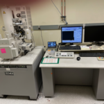
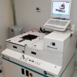
The Tencor Instruments M-Gage™ 300 with the new Upgrade Kit from seller is a Sheet Resistance Measurement System.
The M-Gage™ 300 measures sheet resistance in ohms per square or milliohms per square. If specific resistivity is known, the thickness of the deposited film layer can be computed from the sheet resistance. The choice of measurement data is easily switch selectable, as is the choice of units.
The Tencor M-Gage 300 Sheet Resistance Measurement System can accommodate 125mm (5”) wafers as well as the standard 2″, 3″, and 4″ wafers. 8 inch is available with special fixture.
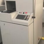
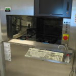
The upgraded Tencor M-Gage 300 Sheet Resistance Measurement System Instruments provides an easier way to operate and maintain this Sheet Resistance Measurement System. The upgraded system is controlled by a Pentium class PC computer running the seller’s new control software, and interacts with the user through a touch screen display. The computer permits the user to operate the machine manually or automatically through a recipe that is programmable by the user.
The new controller allows calibration of the ohm and milliohm measurements within the software. This provides a much easier and faster method to calibrate the upgraded system than by adjusting pots on the back of the Tencor M-Gage 300 Sheet Resistance Measurement System .
There is only one encoder disk for all configurations with the upgraded system. The original Tencor M-Gage has multiple encoder disks depending on the wafer sizes and the number of test points to be tested. Each time the wafer size changes or the need to have different number of measuring points, the encoder disk has to be changed. There is no need to change the encoder disk with the new upgraded M-Gage™ Instruments. The wafer size and the position of the test points are programmed into the recipe by the operator. The original Tencor encoder disks have fixed positions for the test points.
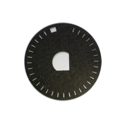
New encoder disk for Tencor M-gage 2 00 Sheet Resistance Measurement System
1.2 SOFTWARE FEATURES
The new upgraded Tencor M-Gage 300 Sheet Resistance Measurement System is controlled by menu commands from the control software. This software allows a great deal of flexibility and control of the new upgraded M-Gage™ Instruments.
The new upgraded Tencor M-Gage 300 Sheet Resistance Measurement System control software features the following:
l Automated calibration of all subsystems from within the control software. This allows faster and easier calibration, leading to enhanced process results.
l Recipe creation. It features a recipe editor to create and edit recipes to fully automate the processing of wafers on the upgraded system.
l Validation of the recipe so improper points will be revealed.
l Storage of multiple recipes, process data and calibration files so that process and calibration results can be maintained and compared over time.
l Passwords provide security for the system, recipe editing, diagnostics, calibration and setup functions.
l Simple and easy to use menu screens which allow an automatic cycle to be easily defined and executed.
l Troubleshooting features which allow engineers and service personnel to activate individual subassemblies and functions.
1.3 MEASUREMENT SEQUENCE
Wafers can be measured at a single point for greatest speed, or at multiple points for the most comprehensive analysis of wafer or film characteristics. In 5-point and 9-point measurements, data points are collected along two perpendicular; axes, as shown below.
During multi-point measurement the wafer is carried beneath the measurement head in two passes. In a 5-point measurement sequence, three points are measured during the first pass. (in 9-point measurements, five points are measured on the first pass.) The wafer is then returned to the loading position, rotated 90°, and the process is repeated. However, the center point is measured only once.
The measurement sequence is programmed by a user defined recipe. The recipe specifies the point for measurement.
Note: It is not necessary to change the optical disk whenever the wafer size is changed or the number of measurement points is required. The optical disk in the upgraded M-gage does not need to be changed.
1.4 OPERATING MODES
The M-Gage has two modes of operation: Manual and Automatic. In Manual Mode the operator steps the wafer through the measurement sequence one point at a time, by pressing a single button. The resistance and the thickness of the measured points are displayed on the computer monitor.
In Automatic Mode the entire multi-point measurement sequence is initiated with the press of a button. The data output is recorded in the computer and can later be printed on a printer. Any serial printer having 20 or more columns can be used. See the following for a sample print-out.
2.0 CONTROLS AND INDICATORS
The controls and indicators are the same as the standard Tencor m-gage, except the computer controls all movements and measurements.
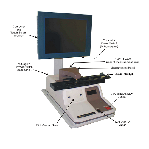
2.1 DESCRIPTION OF M-GAGE FEATURES
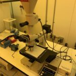
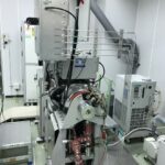
Measurement Head – This houses the non-contact measurement system. Wafers pass between sensors in the upper and lower halves of the head. A gap between the halves allows clearance for wafers up to 1mm (40 mils) thick.
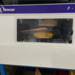
Wafer Carriage – The carriage moves the wafer under the measurement head, positioning it at each data point. It makes two passes under the head for multi-point (5-point, and 9-point) measurements.
l The carriage is ready to accept a wafer when it is in the loading position (to the right of the measurement head).
l The carriage moves to the unloading position (to the right of the measurement
head) when measurement is complete. The wafer can then be removed.
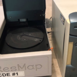
Disk Access Door – This door allows access to the encoder disk. It is no longer necessary to change the encoder disk for different multi-point measurement sequences and wafer sizes. Only one encoder disk is required for all wafer sizes and measurement point positions. This is all controlled by the software.
Power Switch (rear panel) – In the up position this switch turns on the power to the Tencor M-Gage 300 Sheet Resistance Measurement System . Allow 30 minutes warm-up time before making measurements. This switch may be left on indefinitely.
Computer Power Switch – This switch turns on the power to the computer and touch screen monitor.
Ω/mΩ Switch (rear of measurement head) – It is used to select units and range of sheet resistance measurements.
mΩ: 1 to 1999 milliohms/sq.
Ω: 1 to 1999 ohms/sq.
MAN/AUTO Button – It selects operational mode: LED on for Automatic Mode, LED
off for Manual Mode.
START/STANDBY Button – It controls the entire measurement sequence. After loading a wafer onto the carriage, press this button to initiate measurement. (In Manual Mode press once for each point to measure in a 5-point or 9-point sequence.) When measurement is complete, unload the wafer and press once to return the carriage to the
loading position.
Computer Monitor – The computer monitor is the user interface to the new upgraded M-Gage™ Instruments. While making measurements, it shows Sheet Resistance in ohms/square or milliohms/square, as selected by the switch on the rear of the measurement head, as well as thickness.
3.0 MEASUREMENT
Turn on the power to the m-gage and the computer. Allow 30 minutes for warming up.
3.1 LOADING THE WAFER
- The carriage should be in the loading position, to the right of the measurement head.If the carriage is not in the loading position, press the START/STANDBY button to move it there. The carriage will not return to the loading position if it contains a wafer.
- Place the wafer on the carriage between the four locator blocks. If the locator blocks must be moved to accommodate the wafer, see the “Wafer Size Set Up” section.
- Place the wafer between the locator blocks so that it is centered over the circular
platform that rotates the wafer.To assure that the wafer is properly centered, align the major flat with the direction of carriage motion.
3.2 MANUAL MODE
1) Select either ohms (Ω) or milliohms (m Ω). Use the switch on the rear of the measurement head.
2) Press the MAN/AUTO button so the LED is off. This indicates the m-gage is inmanual mode.
3) Momentarily press the START/STANDBY button. The carriage will move the waferunder the measurement head to the first point in the measurement sequence. The sheet resistance and the thickness of the measured point will be displayed on the computer monitor.
4) For multi-point measurements–press START/STANDBY once for each point in themeasurement sequence. The wafer will be advanced to the next point and the data forthis location will be displayed. Multi-point measurements (5-point and 9-point) are made along two axes. After the measurements are completed on the first axis, the carriage will return to the starting position, the wafer will be rotated 90°, then measurements will resume along the other axis.
5) When the measurement sequence is complete the carriage will move to the right until the wafer is out from under the measurement head in the loading/unloading position. The wafer can be removed from the carriage after it has reached this position.
Carefully remove the wafer from the carriage.
3.3 AUTOMATIC MODE
Automatic mode allows the m-gage to go to all of the measurement points and take measurements without stopping. After the last measurement point has been measured, the carriage will move to the unload position. All data measurements are recorded in the computer for later retrieval, inspection and, if desired, a print-out of the measured points can be printed on an external printer.
1) Select the desired recipe in the Process for Production screen or the Process for Engineer screen.
2) Make sure the MAN/AUTO LED is on. Press the MAN/AUTO button on theM-Gage control panel until the LED comes on.
3) Press the START/STANDBY button. The entire measurement sequence will beperformed without further operator intervention. When the sequence is complete, thewafer will be moved to the unloading position. The wafer will pass under the head two times. After the first pass it will be returned to the starting position, rotated 90°, and then carried under the head a second time.
4) Carefully remove the wafer.
5) If similar wafers are to be measured, repeat Steps 1 through 4 for each wafer.
All the Tencor M-Gage 200 Sheet Resistance Measurement System trademarks belongs to KLA-Tencor which was formed in April 1997 through the merger of KLA Instruments (KLA) and Tencor Instruments (Tencor), two long-time leaders in the semiconductor equipment and yield management system industry. , the original equipment manufacturer. All rights reserved.