Description
SOLD
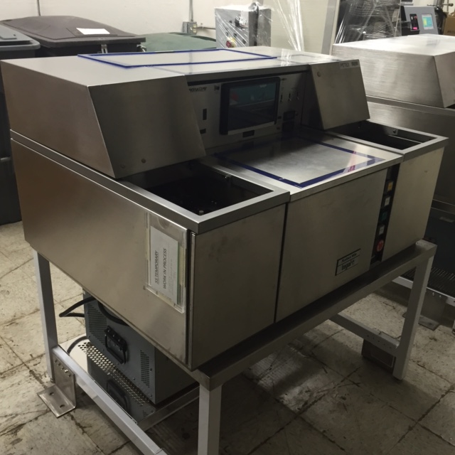
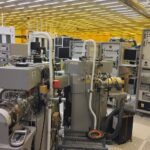
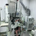
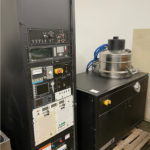
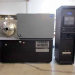
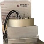
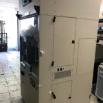
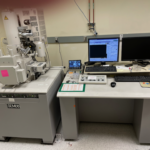
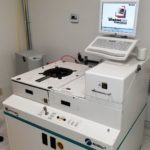
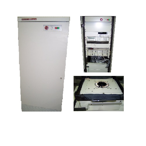
Kurt J Lesker PVD 75
The item is only for end user. The item is subject to prior sale without notice.
KJLC PVD 75 THIN FILM DEPOSITION SYSTEM
- PVD Process Chamber including the following:
- D-shaped, 304 SS, 24” high X 14” wide/deep
- O-ring sealed, hinged, front access door (nominal dimension 14” x 24”)
- Large access viewport and replaceable viewport insert on door
- Flexible process ports to allow the installation of process equipment
- Appropriate pumping, gauging and instrumentation ports
- Note: no chamber liners are provided
- Vacuum Pumping including the following:
- 210 l/s speed control compound turbo pump (no high vacuum isolation valve is provided or required)
- 2.a. Optional 500 l/s speed control turbo pump (no high vacuum isolation valve is provided)
- 2.b. Optional CTI-8F 1500 l/s cryopump, compressor and a pneumatically isolation gate valve. Automatic regeneration capability is included through touchscreen controller or PC control package
- 2.c. Optional 3-position pneumatically actuated isolation gate valve to adjust pumping speed during sputtering when using cryo pump. This option is provided for use with a cryo pump instead of the 2-position valve included with option 2.b
- Oil-sealed mechanical 5.7CFM roughing pump and foreline valve (system is roughed through the turbopump)
- 2.d. Optional Dry roughing pump (in place of oil-sealed mechanical pump)
- 2.e. Optional Fomblinized mechanical pump, including Fomblin charge (in place of oil-sealed mechanical pump)
- Foreline trap, mist eliminator, roughing valve, and all applicable roughing hardware
- Independent, pneumatically actuated vent valve
- Vacuum Gauging including the following:
- Wide range vacuum gauge (Ion gauge and Pirani)
- Readout is integrated into system control panel
- All mounting/connection hardware, adapters, etc.
- System Framework including the following:
- Closed system support frame (46.75” wide x 34.20” deep x 74.50” high)
- Enclosed power distribution
- Leveling pads
- Water Manifold including the following:
- Manifold for water distribution to system components
- Shut off valves
- Interlocked flow switches to critical components
- 1” NPT connection
- 5.a. Optional recirculating water chiller. Tek-Temp, 6 gpm, 10,000 Btu, 60 PSI
- Power Distribution including the following:
- Single service drop (208VAC, single phase, 30 Amps based on configuration)
- Component wiring is routed to a centralized power distribution panel
- EMO protection
- Appropriate safety interlocks
- Note: A dedicated earth ground is required
- Note: Electron Beam and thermal evaporation power supplies may require a dedicated service
- 6.a. Optional 208VAC, three phase 60 Amps power distribution (as required based on total load of selected options)
- Documentation
- Engineering drawings (including mechanical assembly, vacuum schematic, water flow schematic, electrical design) and an operation manual are provided in both paper and CD version.
Process equipment extras:
- Sputtering Source(s)
- Up to three Torus magnetron sputtering source flange assemblies that include the following:
- 8.a. Torus 4 magnetron sputter cathode mounted to an adjustable 3/4” tube
- O-ring sealed compression fittings to adjust source-to-substrate distance
- A pneumatically driven deposition source shutter
- 8.b. Optional flex mount accessory for Torus source
- As an option, high strength magnet assemblies can be purchased to sputter 2”, 3”, or 4” magnetic targets
- Gas injection ring and deposition chimney are available as an option
- 8.c. Torus 6 magnetron sputter cathode, internally mounted. Includes pneumatic swing shutter
- Sputtering Source Power Supply Options
- 9.a. KJLC 300 W RF power supply with manual match network
- 9.b. KJLC 300 W RF power supply with auto match network
- 9.c. KJLC 600 W RF power supply with automatic matching network and control panel
- 9.d. Advanced Energy 500 Watt DC power supply
- 9.e. Advanced Energy 1.5 kW DC power supply
- 9.f. Advanced Energy 6 kW Pinnacle power supply (for use with 6” sputtering source)
- 9.g. Advanced Energy SPARC-LE 20, arc repression unit for pulsed DC sputtering when used in conjunction with a 1.5kW DC power supply.
- 9.h. Advanced Energy SPARC-LE V variable frequency arc repression unit for pulsed DC sputtering when used in conjunction with a 1.5kW power supply
- 9.i. A 3-position DC switch to allow manual sequencing of deposition sources from a single DC power supply
- All power supplies are provided with rack mount kits and all connection cables
- Static (Top Mounted) Substrate Fixture (available with optional configurations) as below:
- Accommodates a single substrate up to 12” diameter using a simple disk shaped stainless steel platen.
- 10.a. Optional variable speed, motor driven rotating platen (up to 20 rpm) for primary rotation of the substrate
- 10.b. Optional custom stainless steel substrate holder for ¼” diameter x ¼” high substrates. Holder will accommodate 240 substrates.
- Other custom configurations are available at an additional cost and are priced on request
- Heating Stage for heating and Control of Substrate Temperature
- Heats the backside of substrate fixture and is supplied with thermocouple feedback and control of temperature to:
- 11.a. 150° C
- 11.b. 350° C
- Manual Process Gas Inlet:
- Two channels of needle valve gas inlet
- 12.a. Optional MKS 626A Baratron 100 mTorr pressure transducer and manual readout
- System vent and purge pressure regulators
- Note: speed control turbo regulates pumping speed
- Process Gas Inlet/Pressure Control including the following:
- Two MKS 1179 flow controllers, all cables, and upstream pressure control electronics
- MKS 626A Baratron 100 mTorr pressure transducer
- System vent and purge pressure regulators
- Note: speed control turbo regulates pumping speed
- Film Thickness Monitor or Control including the following:
- 14.a. Quartz crystal thickness monitor package with a single (standard sensor) crystal head
- 14.b. Film Thickness Control including the following:
- One quartz crystal thickness controller package
- One single crystal, crystal head (located near the substrate)
- 14.c. Optional additional single crystal head(s)
- 14.d. Optional upgrade to shuttered single sensor head(s)
- 14.e. Optional dual sensor head
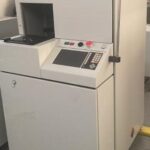
- System Control
- 15.a. Manual Control
- One button pump down and vent using a touch screen controller
- Touch screen controls valves and shutter assemblies
- Manual front panel control of power supplies, switches, etc.
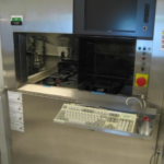
- 15.b. Basic Computer Control
- PC-Based control system (Windows XP Professional)
- KJLC “C-Ware” Visual Basic based Software
- Rack Mounted PC with touch-screen flat panel monitor
- Rack Mounted keyboard and mouse in drawer
- Screen layouts follow the guidelines of SEMI E95-0200 (Specification for Human Interface for Semiconductor Manufacturing Equipment)
- PC provides supervisory computer control over vacuum pumping, vent, and cryo pump regeneration cycles (where applicable). It also controls deposition power supplies MFC’s, substrate heating, and substrate fixture motor rotation (where applicable).
- Includes Graphical User Interface (GUI) display of the following system parameters, If applicable:
- Vacuum Screen
- Visual display of valve position
- Visual display of pump status
- Display of vacuum status
- Deposition Screen
- Indication of shutter position
- Deposition source status
- Source material & target life log
- Gas Screen
- Mass flow controller modes
- Indication of gas valve status
- Display of pressure control settings and values
- Motion Screen
- Display & input of speed and velocity profiles
- Display & input of PID control parameters
- Cooling Screen
- Water flow switch interlock status
- Heating Screen
- Heater setpoints & control parameters
- 15.c. Computer Control Including Recipe Features
- Provides for fully automatic process control
- Recipe creation & storage using Microsoft Access database
- Programming / control is accomplished via a keyboard/mouse or pop-up keypad on touch screen
- Three levels of password protection with user assignable access to recipes
- In addition to GUI features in 18.b., the following are provided
- Recipe Database Screen
- Allows selection of a “pre-written” recipe
- Allows editing of existing recipes
- Copy function for existing recipes
- Configurable Datalogging function, exportable to Excel
- User log, exportable to Excel
Specifications
- Process Chamber Volume 75 liters
- Process Chamber Geometry D-Shaped, 14” (365mm) wide X 14” deep (365mm) X 24” (610mm) high
- Process Chamber Construction 304L Stainless Steel with 6061 Aluminum Hinged Door
- Cabinet Construction Carbon Steel, Fully Enclosed, Gray Powder Coat Finish
- Deposition Sources (Available in various combinations)
- Torus® Magnetron Sputtering Cathode
- 4-Pocket 8cc Electron Beam Source
- Multiple Boat Source Thermal Evaporation
- LTE Organic Material Evaporation Source
- Deposition Orientation Sputter Up or Down, Evaporation Up
- Substrate Cleaning Ion Source or RF Bias
- Substrate Size (max) Single 12” (300mm) with optional 20 RPM max variable rotation
- Substrate Heating Quartz Lamp or Resistive Element
- Standard Vacuum Pumping 260 l/sec Turbo Pump, Optional 685 l/sec Turbo Pump, or 1500 l/sec Cryo Pump Available
- Gauging Wide Range Vacuum Gauge
- Base Pressure Turbo Pump (CDE) 5 x 10⁻⁷ Torr (6.7 X 10⁻⁷ mbar)
- Process Gas 2 Channel Manual with Optional Mass Flow Control with Pressure Control
- System Control PC-Based HMI, with optional Recipe Control and Datalogging
- Required Power (typical, based on options) 208VAC, 3Ø, 50/60 Hz; Optional 380VAC, 3Ø, 50/60 Hz
- Overall Dimensions (approx) 47” (1194mm) wide X 35” (889mm) deep X 75” (1905mm) high
- Weight (approx) 1,800 lbs (816 kg)
SSEB380